Wednesday, February 12, 2014
Dads Benchtop Bench Part II

Once I had finished the legs and had milled the top, I made the twin screw vise out of a big hunk of oak Kari Hultman gave me. It was about 10/4 to begin with, and after all of it’s milling, the vise was still a heavy 8/4. This was a bit thicker than Miller’s plans from Fine Woodworking, but I figured giving up 1/2 of vise capacity wasn’t worth the extra work of planing off 1/4” from each jaw.
 |
| The milled vise jaws. |
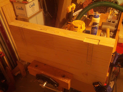
With the vise jaws milled, I then set out to drill the vise screw holes and make the mortises to countersink the vise screw nuts. I used Miller’s side to side spacing to determine the screw location, making sure that they were clear of the legs before committing (I had made the width of my legs slightly wider than Miller’s. The screws are simply centered, top to bottom.
With the vise screw locations marked on one (1) of the jaws, I set them on top of each other on my drill press. I used an 1/8” bit to drill through the entire upper jaw and about half the lower jaw (I ran out of bit length). These 1/8” holes served as center guides for the larger bits I would use to make clearance for the vise screw (about 5/8”) and the vise screw nut (about 1-1/4”).
 |
| Drilling the pilot holes for the vise screws. |
After checking that the vise screws fit in their holes, I set the vise screw nuts in their holes. I traced around their flanges and pulled them out.
Then I used my DeWalt DWP611 with an 1/8” upcut spiral bit to route out for the screw flanges. To set the depth, I set the router on my bench and brought the bit down to the bench. Then I loosened the depth guide and slid the flange between the top and the turret. I then tightened the stop and pulled the flange out. By lowering the router until the stop hit the turret, I had set the depth exactly as deep as the flange.
 |
| Plenty of clearance. |
I then simply routed free hand. To ensure that the flanges fit, I made sure to go outside the lines which were drawn tight.
 |
| Too proud. |
When I installed the vise screw nuts, I found that they fit perfectly within the routed out areas. I also found that they stuck out proud of the inside face of the vise jaw. I had to remove them and cut off the excess with a grinder in order to fit them properly.
 |
| Being shamed into fitting. |
With the vise nuts installed, I assembled the vise by inserting the vise screws through the front jaw into the rear jaw and snugging them up. Then I laid the vise in place, letting the screw threads rest on the underside of the benchtop. I marked the screw locations with a pencil and took out the DWP611 again.
 |
| I actually routed the nut clearance first. |
I used the router freehand to remove a clearance hole for the screw threads and I relieved a small amount on the edge to give just a little extra clearance for the back of the vise nuts.
 |
| Ready to receive the screw. |
With the benchtop milled to accept the vise, I went back to complete the front jaw.

Subscribe to:
Post Comments (Atom)
Hello everybody, If you love building sheds like me, here's a great site for you to download shed plans:
ReplyDeleteGET ACCESS TO 12,000 SHED PLANS
Get instant access to 16,000 woodworking plans.
ReplyDeleteTeds Woodworking has more than 16,000 woodworking plans with STEP-BY-STEP instructions, photos and drafts to make all projects smooth and easy!